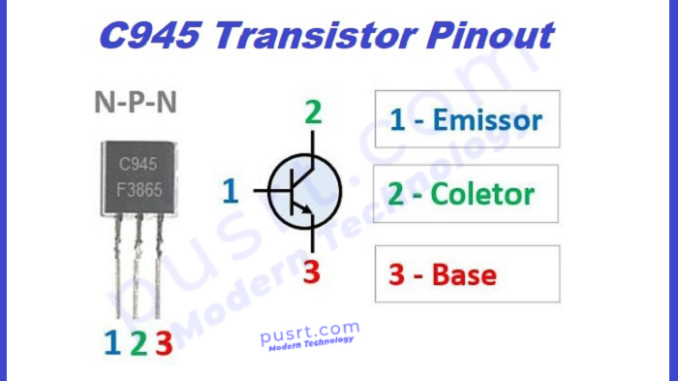
C945 transistor is a small-signal NPN (Negative-Positive-Negative) bipolar junction (BJT) device. It is mostly used in electronic circuits for switching and and amplification. It is an old transistor now there are many transistor that comes as an alternate of transistor c945 such as BC547,BC548,BC549 and etc.
C945 Transistor Pinout
Almost all transistors are consists of 3 terminals or pins C945 pinout detail is given below in the picture and table. These pins are used to connect the transistor to other electronic components in electronics circuits. C945 transistor pinout are as follows:
Transistor C945 Pinout description
Pinout description of c945 are given below in the table to understand quickly.
| Pin Number | Pin Name | Description |
| 1 | Emitter | Emitter is used for Current Drains out normally connected to ground |
| 2 | Collector | Collector is used normally for Current flows |
| 3 | Base | Base is used to Control the biasing of the transistor |
C945 Features
The basic features of C945 are given below.
- Package Type: TO-92
- Transistor Type: NPN
- Max Collector Current(IC): 150mA
- Max Collector-Base Voltage (VCB): 60V
- Max Emitter-Base Voltage (VEBO): 5V
- Max Collector Dissipation (Pc): 400 mili-Watt
- Maximum Collector-Emitter Voltage (VCE): 50V
- Maximum Transition Frequency (fT): 200 MHz
- Min & Max DC Current Gain (hFE): 70 – 700
- Maximum Storage & Operating temperature should be: -55 to +150 Centigrade
C945 Transistor Equivalent
Some possible equivalents or alternate of transistor C945 are:
- 2N3904: It is also widely used NPN transistor with almost similar characteristics to the transistor C945.
- BC547: This is another widely used NPN transistor with similar characteristics to the C945.
- 2N2222: NPN transistor that has similar characteristics to the C945 and can be used as alternate of c945.
Complement of c945 transistor
The complementary of a transistor C945 would be a PNP (Positive-Negative-Positive) transistor with similar characteristics but opposite polarities. A commonly used PNP transistor with characteristics similar to the C945 is the 2N2907 transistor.
Transistor C945 Applications
The applications of c945 are given below in the list
- Pre-amplifiers
- Common Emitter Amplifier Circuit
- Low current switches
- H-bridge circuits for low power motors
- Audio frequency amplifier circuits
- Oscillator circuits
- Voltage Regulation
Where & How to Use C945
The C945 has a good DC gain low noise type. It is perfect for use in audio preamplifier and amplifier circuits. Mostly BJT transistors have a saturation voltage of 0.6V, but the C945 has a saturation just 0.3V, therefore it can be used in low voltage circuits. It can also be used in RF circuits with a frequency of less than 200MHz.
Transistor C945 Package
The C945 transistor typically comes in a TO-92 (Transistor Outline 92) package. This package is a small, three-lead plastic package. Some characteristics of the TO-92 package:
- Pinout: The three leads of the TO-92 package are usually arranged as follows:
- Collector (C)
- Base (B)
- Emitter (E)
- Number of Leads: The TO-92 package has three leads or pins.
- Size: The TO-92 package is relatively small and compact, making it suitable for through-hole PCB (Printed Circuit Board) mounting.
- Plastic Encapsulation: The package is made of plastic, which provides electrical insulation for the internal components and ensures it is physically durable.
- Mounting: TO-92 transistors can be easily mounted on a PCB using standard techniques like soldering.
C945 Transistor Dimensions
The dimensions of a C945 in a TO-92 package are relatively standard for transistors in this package type. Here are the typical dimensions for a TO-92 package, which should give you a good idea of the size:
- Overall Length (L): Approximately 5.33 mm (0.210 inches)
- Overall Width (W): Approximately 4.33 mm (0.170 inches)
- Overall Height (H): Approximately 5.84 mm (0.230 inches)
C945 Datasheet
Frequently Asked Questions
Other possible questions about 945 are given below
How does C945 work
The transistor c945 is NPN (Negative-Positive-Negative) bipolar junction transistor. It works as an electronic switch or as an amplifier. The working of c945 is given below in both situation Switching mode and amplification mode.
Switching Mode:
- OFF State: When no current flows into the base terminal (B), the transistor is in its OFF state. In this state, the transistor does not conduct, and no current flows from the collector (C) to the emitter (E).
- ON State: To turn the transistor ON, you apply a small current (base current) to the base terminal (B). This forward-biases the base-emitter junction (BE). When the base-emitter junction is forward-biased, it allows current to flow from the collector to the emitter. The transistor is in its ON state and acts like a closed switch, allowing current to flow from C to E.
Amplification Mode:
- The C945 transistor can also be used as an amplifier. In this mode, a small input signal (usually connected to the base) is amplified to produce a larger output signal (across the collector and emitter). This process occurs as follows:
- An input signal is applied to the base terminal. This signal controls the current flowing through the base-emitter junction.
- The base-emitter junction acts as a diode, and its conductivity is influenced by the input signal. As the input signal varies, it modulates the current flow in the base-emitter junction.
- This change in base current, controlled by the input signal, results in a much larger change in collector current. The transistor amplifies the input signal to produce a larger output signal.
How do you test a C945 transistor?
Transistor as a Switch (On/Off Test): This test checks if the transistor can act as a switch:
- Turn off the Power:
- Identify the Pins:
- Set Multimeter to Diode Test Mode:
- Testing Collector and Emitter Junctions:
- Testing Base-Emitter Junction:


Leave a Reply